Can You Set Draw Order by Layer in Autocad Lt
In this exercise, you will open a drawing based on an Architectural template and use layers to assign properties to objects.
Make sure you have our free AutoCAD class files downloaded prior to beginning the tutorial.
Exercise Preview
In AutoCAD, layers are used to separate and organize objects into different categories. Layers can be locked and hidden. Layers can also be used to assign the line weight (width), line type, color, and transparency to the objects on the layers.
This practice is referred to as Property by Layer, and is usually the best way to assign these properties to your objects. You can also assign properties to objects individually, referred to as Property by Object, which will be covered later in this course.
Unlike other programs, layers in AutoCAD have nothing to do with stacking order, and in a literal sense, they aren't really layers at all! Layers can be created as needed, but they are usually defined by Template files (.dwt). See a preview of what you'll be producing below:
Using Layers in a File
1. Open the file Layers-Architectural.dwg. This Drawing file is based on an Architectural template with layers appropriate for architectural drafting.
2. If you look in the Layer Panel or Toolbar, you will see that the layer indicated in the Layer Control is A-Walls. If no objects are selected, the layer shown in the Layer Control is the current layer. The current layer is the layer new objects will be created on, so it's very important to keep track of what the current layer is at all times. Note that all the objects in the drawing of the tool shed are the same color. This indicates that all the objects are on the same layer. Select any object in the drawing. You will see that the layer indicated in Layer Control is 0. If any objects are selected, the layer shown in the Layer Control is the layer those objects are on. If you select multiple objects on different layers, the field in Layer Control will be blank. Layers can be used to define properties of objects on those layers, specifically Line Weight, Line Type, and Line Color.
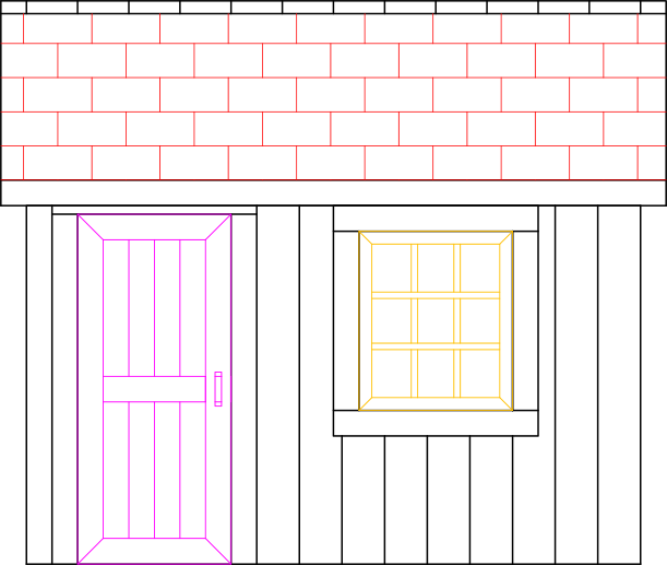
3. All of the objects in this drawing are currently on layer 0. Every AutoCAD .dwg and .dwt file has a layer named 0. It cannot be named or deleted. Layer 0 is typically black, but many users will make Layer 0 a different color so you won't put anything on Layer 0 by mistake. You can change what layer an object is on by selecting the object and changing the layer in Layer Control. Select the window on the tool shed. Expand the Layer Control and change the layer from 0 to layer A-Windows. You will see that the window will change color to match the color of the layer. In most AutoCAD drawing, the primary purpose of color is to indicate what layers objects are on. When you print or export to a .pdf, you can use Plot Styles to make objects be colors that don't conform to the layers they are on, typically black. This will be discussed later in this book.
4. Select the door and change its layer to A-Doors. Once again you will see its color will change to match the layer.
5. Select any of the shingles toward the center of the roof. The shingles are a Hatch, which is a pattern that can fill an area. Hatches will be covered later in this book. Look in the Ribbon, you will see that the current Ribbon Tab is the Hatch Editor. Select the Home Tab so you can access the Layer Panel to move the Hatch to the Hatch Layer.
6. Now all the objects left in the drawing are on Layer 0. Select any of those objects and then Right–click. Choose Select Similar from the Right–click menu to select all the objects on Layer 0.
7. Select Elevations in the Layer Control to move all the objects to the Elevations layer.
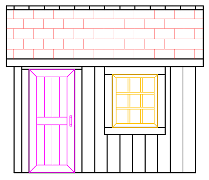
8. Line weight, or width of the line, is another property that can be assigned to objects with layers. Click on the Customize button in the Status Bar, and select LineWeight from the flyout menu, if it isn't already checked. The Lineweight button  will appear in the Status Bar. The button controls whether or not line weights are visible on the screen. The line weights will always appear in the final print or .pdf file. Click the Lineweight button in the Status Bar so that it's highlighted. You will see the varying line weights appear in the tool shed drawing. Note that the line weights as they appear on the screen do not necessarily represent how they will appear on the final print because they are relative to your screen and not the final page size.
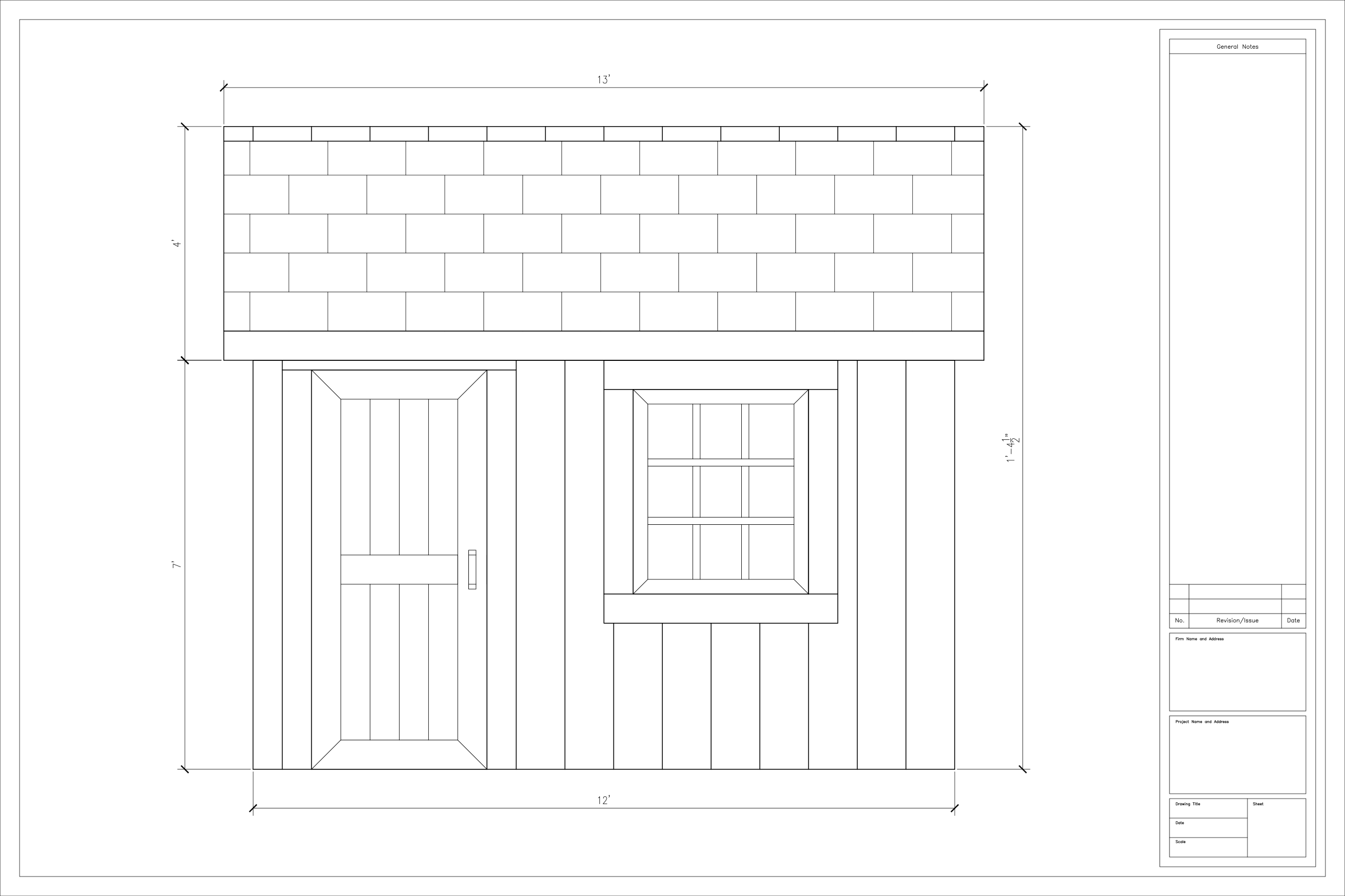
9. Layers can also be locked or hidden. This is referred to as changing the Layer State. Click on the D-Size Layout Tab. You will see how the tool shed will appear printed on D-Size paper with a Title Block. Expand the Layer Control. You will see a snowflake on the Dimensions Layer. This means the layer is frozen and objects on it are hidden. Click on the snowflake and it will turn into a sun. This means the layer is thawed and you will be able to see the dimensions on the layer.
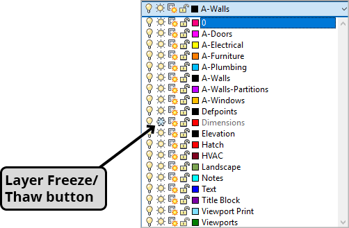
NOTE: The screenshot above is the D-Size Layout with the Dimensions layer thawed.
10. Enter the PREVIEW command. A window will appear displaying what the final print will look like, as shown in the D-size layout plot (print) preview below. Note that all the objects are black, and not colors assigned by the layers. Zoom in to see the different thicknesses of the lines according to their line weights. Click on the X in the upper left of the Preview Window to close it.
11. Close and save the file.
Learn More About AutoCAD
Draft blueprints and mechanical drawings like a pro through our suite of robust AutoCAD courses in NYC. Classes are small and scheduling flexible, so sign up today!
Can You Set Draw Order by Layer in Autocad Lt
Source: https://training-nyc.com/learn/autocad/assign-color-line-weight